

Cal Poly Featherweight Cycle 2022
The Challenge
Competition Website:
https://nfpafoundation.org/fpc/vehicle-challenge/
Sprint Race
Timed event where the vehicle must travel between 400 to 600 feet.
Teams must use the Accumulator Discharge circuit of the hydraulic system.
Endurance Challenge
20 Mins of Riding to go the longest distance.
Requires 1 Complete stop using the regenerative braking ciruit of the hydraulic system. Then the vehicle must move at least one vehicle length with the regenerated energy.
Efficiency Challenge
Vehicle must Travel at least 100 ft
Efficiency gets quantified as Work output to Energy Stored.
No rules about what hydraulic circuit to use.

Senior project at Cal Poly is a 3 quarter project were you go through the complete design cycle as a group. The first quarter was online(Due to COVID-19) and is all about research, prototyping, and design iteration. We strongly used decision matrix's for every design within the entire assembly to make good design choices for manufacturability, durability, and to be competitive. The second quarter is all about doing engineering analysis on the necessary aspects of the design, structural prototype, and finalizing the design and setting up a manufacturing plan/cost analysis to provide for sponsor. The final quarter will be all manufacturing, and testing specifications of the design. In our group of 5 students, one person is really good with mechatronics, another is really good with CAD, and another is a 3 time BMX racing national champion who loves manufacturing. As team leader I try to lead by example and I have worked a bit with all areas of the design, but I took main responsibility of the hydraulics design of the bike. As team leader I try not to overstep and always listen to the ideas of the team, there has been often so many ideas that the main thing I had to do is steer the directing towards manufacturability and ability to execute. The other main thing I've done is work on the projects worst problems, the problems no one else wants to do because they are not familiar with, such as the hydraulic pump not working, the pneumatic seat sliding and locking mechanism along with pneumatic circuit design, composite manufacturing, and steel inserts for composite interfacing on the frame.

Composite Frame Design
The name Featherweight Cycles would not be suitable if there was not a lightweight, high strength carbon fiber frame. This frame consists of custom steel inserts which bond all composite tubes together, with two long square intermediate modulus carbon fiber tubes running down the length of the of vehicle. It also features two perpendicular tubes which locate the front headsets, made of high strength round carbon fiber tubes. The connection inserts for the wheels are what is known as bicycle down tubes that are welded to steel tubes and will be inserted into the composite tubing. Finally, there will be a high strength carbon fiber tube that is extended out to hold the cranks at an angle that will be optimally set for the rider. Below are some of the many critical parts designed for the frame assembly.
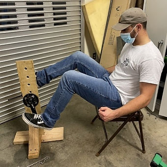
The process to figure out the crank angle and seat position is important as it will affect the performance of the rider when in direct drive. The previous team had an issue with the seat position being too close to the pedals, but the rider should be able to operate the vehicle comfortably by doing this structural prototype.
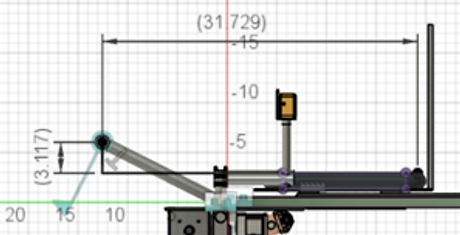
The distance from the seat backrest to the center of the front crank will be ranging from 31.73” to 39.32”, and the crank angle will be 27° relative to the seat as described in Figures 5.2.6 and 5.2.7. The ideal seat distance that our rider feels the most comfortable is 38”, which is within the range of the possible seat distances.

The mechanism is two handled, and connected by a tie rod, located underneath the front pump, and it utilizes the mechanics of an Ackermann steering linkage. Components that will be part of the steering mechanism consists of 5 custom made parts and the rest are parts that will be reused or purchased in order to complete the assembly of the front mechanism.

The mounting portion of the handlebars are made of 1.25” aluminum tubing that will attached to each front shaft with handlebar stems on both sides of the front assembly. Welded to this tube will be a 7/8” aluminum tube and mounted perpendicular to the 1.25” tubing for the purpose of a grip for the rider and to ensure the front brake mounts on the correct cross-sectional area. A structural prototype was created to replicate the handlebars and to understand the manufacturing process of notching steel tubes and welding them together.

Featherweight Cycles is mainly concerned with the application of these front tubes as their location on the frame will take the highest dynamic loads induced by cornering at high speeds and the overall weight of the vehicle and rider. While trying to minimize the weight of the front tubes, the team also attempts to provide as much stability to the front tubes as possible to prevent any fracture failures induced by the dynamic loads. To achieve this, Featherweight Cycles chose the steer tube assembly on the left side in Figure 5.2.7 to be made of steel and welded together. To minimize the weight of the tubes, the horizontal tube in Figure 5.2.8 will be made of high strength carbon fiber and will be bonded to the 5-way-insert steel tube with an epoxy adhesive.
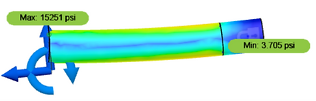
Featherweight Cycles choose to do hand calculations and a FEA analysis on the horizontal carbon fiber tube due to the high induced loads. The material properties were assumed to be Aluminum 6061-T6 because carbon fiber material properties vary depending on part to part. Aluminum 6061-T6 will be a conservative assumption. The FEA analysis shows the max stress to be 15 ksi, which the carbon fiber tubing should handle with ease and with a conservative safety factor. The Aluminum resulted in a safety factor above 2.0 for yield strength.
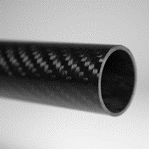
For the composite tubes located in the front of the vehicle holding up the front down tubes, and the cranks, is round carbon fiber tubing. The outer ply of material on this tube is a 2x2 twill weave which will prevent fiber breakout better than unidirectional material. Thus, these tubes provide an ideal surface for machining. The core of this tube is almost always comprised of layers of unidirectional plies which makes most carbon fiber fabric & unidirectional tubes ideal for bending and compression applications.

The square long tubes going back from the front of the bike, are carbon fiber square tubes manufactured using multiple layers of pre-preg carbon fiber materials. The term pre-preg means the carbon fiber is pre-saturated with the resin adhesive and frozen before it is formed to the mold it will take. The square tubing chosen is 0.46 pounds for 66” of tube and is made with intermediate modulus carbon that has a 3/8” medium checkered weave.
Pneumatic System Design
Pnuematic implementation on the fluid powered vehicle is now a requirement for the competition. Most teams seem to make a pneumatic emergency brake, but Featherweight wanted to be ambitious in this area of the design. The pneumatic system implementation will be an adjustable seat subassembly. The system will be composed of an air tank reservoir, polyurethane hose, quick release tube couplings, a 2-way pneumatic actuator, 1x 5/3 solenoid valve for the seat adjustor, 1 x 2/2 solenoid valve for the locking mechanism, electrical system to power the solenoids, and pressure regulators. Pictured below is how the double sided piston will be mounted to the seat and the pneumatic circuit drawn out using AutoCad.

The 2-way actuator is attached to the bottom of the seat and will be visually hidden when looking at the vehicle. Hoses will be routed from the air tank to this actuator, and to the locking actuator. The locking mechanism design was the hardest to come up with, but it utilizes a traditional car seat rail system that was modified to lock and unlock using a linear actuator that translates to rotational motion as shown above.
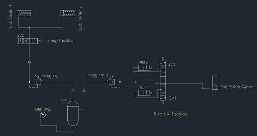
The pneumatic schematic below summarizes the pneumatic subsystem assembly. It displays the relationship between components and their physical location. This schematic does not include the electrical wiring required to operate the entire system.
Hydraulic System Design
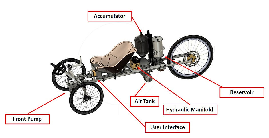
The Hydraulic system is very complex and consists of a front positive displacement pump, rear two-way motor, reservoir, accumulator pressure vessel, high pressure lines, solenoids, check valves, and manifold. The reservoir is being custom made out of aluminum, and hydraulic hardline will be custom made to increase the efficiency of the flow. Below are schematics that map out the solenoids trigger for each drive mode of the vehicle. The dashed line around the outside of all the solenoids represents the hydraulic manifold boundary in the circuit. Thus, all the components outside of the line represents the outside components like the reservoir, manifold, pressure transducer, relief valve, pump, and rear two-way motor. The red arrows represent the direction of flow in the configured drive mode.

Direct Drive Circuit
The above figure shows the hydraulic circuit in the direct drive mode which is when all the solenoid's default position for the bike. In other words, none of the solenoids need to be energized to be able to use this mode. This mode will be utilized mainly during the endurance challenge of the competition. This mode is when the driver pedals the bike, it moves the fluid through a check valve, and on the other side of the check valve the fluid will build pressure that will drive the rear motor and turn the rear wheel propelling the bike forward. This is why it is called direct drive mode, as the user pedals the bike moves in response, but it is rather extremely inefficient in relation to a normal chain drive bike.

Accumulator Discharge Circuit
The hydraulic circuit is in boost mode, otherwise known as accumulator discharge mode in which all the built-up pressure in the accumulator is released to the rear motor of the bike, propelling the vehicle forward. This mode will be used in the efficiency test and sprint race of the competition. Two solenoids need to be energized to use this configuration, one of which is named SV5, regulates the flow through it to control the speed and pressure of the fluid through the rest of the circuit.

Pedal to Charge Mode
The pedal to charge mode will be utilized most definitely for the sprint and efficiency tests of the competition as the driver pedals the front pump the fluid will flow through check valves up into the accumulator and build pressure. This mode can be utilized when the bike is stationary before races or during races if it is desired to charge the accumulator intermediately. The pedal to charge mode allows the driver to pedal and charge the accumulator directly through the front pump, and the SV1 and SV2 solenoids need to energize to use this mode. The accumulator can and will be charged to a maximum pressure of 2800psi, thus all the lines and fittings of the hydraulic system need to be rated much higher than this to ensure safety of the system.

Regenerative Brake Mode
This is braking regeneration mode, in turn switches the accumulator into charge mode building up pressure. This mode uses the translational velocity of the vehicle and the friction of the ground to turn the rear motor, effectively turning the rear motor into a pump, pumping fluid back up into the accumulator. This mode effectively acts as a brake as the pressure gets higher in the accumulator, the bike slows down. This mode will be harnessed in the endurance test of the competition and must show that the vehicle can move forward from the regeneration mode of the circuit.
Mechatronics Design

Touchscreen User Interface
Located on the Handle Bars, the touchscreen user interface allows the driver to change drive modes of the hydraulic circuit, monitor what solenoids are currently activated, real time accumulator pressure, and current speed of the vehicle.

Communication of Signals
The following components will be used from for the mechatronics assembly on the vehicle.
Custom user interface
Hydraforce PLC valve driver
Data acquisition
Network electronics over CAN bus
Quick press manual buttons
The custom interface holds the controller that will be the master to all other components of the mechatronics system. It will signal to the Hydraforce valve driver to open the correct solenoids to open as directed by the user, and pick up the speed and pressure sensor readings to display to the user as desired.
Final Vehicle & Results

