Laser Engraver Project at KNT Manufacturing
KNT Manufacturing is a world class precision manufacture that serves primarily the semiconductor industry, but also serves aerospace, biotech, and more. Engineers at KNT primarily work on RPM products or first article inspections to refine the manufacturing process to customer print. They also work on KAIZEN projects, reworks, and operation method protocols within the company. As a manufacturing engineer intern, I dipped into each of these areas a bit, I did some OMS's, worked on a KAIZEN project, and made fixtures for high procession welding parts. Unfortunately I cannot get into the details of those projects due to a non-disclosure agreement, but I can talk about a side project I worked on with Eric Ramos, a laser engraver calibration project.
Laser Engraver Project Break Down
The laser engraver machine we worked on, wasn't working correctly when we started. It would engrave, but the script would come out very poorly and it seemed as if the timing was very off between the hardware and the software. It took a lot research to figure out what was wrong, as it is a Chinese laser machine, and the documentation of the machine was very poor. The layers of the Operation method sheet we wrote is broken down below. With detailed documentation, and with correct material depth of cut, KNT can use this laser engraver machine to engrave part and serial numbers on small parts in-house, instead of using a out of house service provider. Thus this project has the potential to save a lot of time and money for the customer and KNT manufacturing. Me and my partner Eric Ramos worked on this project together and we did a lot of research independently but with constant communication to quickly solve problems. We worked on the laser together in the room some days for 6 hours straight together, trying things and iterating to solve issues as well as working on other work related projects together.
Machine Start Up & Layout
Machine Start-up
Safety
General Software Layout
Importing Images/Vector Files
Calibration
Finding Focal Length
Scaling Calibration
Timing Calibration
Laser Engraving
Hatch Settings
Material Settings
Red-Light Operation
Flat Surface Engraving
Curved Surface Engraving

Machine Start-up & Safety

Turning the Laser On
When turning on the laser, the user must power on the computer, remove the laser lens cover, put on protective eye wear, and turn on the green buttons upon the control panel on top of the desk. There is always the emergency stop button, on the control panel that will shut down all power to the machine at once for emergencies. The Rotary attachment button is only for the user if they want engrave on a curved surface, therefore it should only be turned on if that is the case. Eyewear should always be on when operating the laser as it can cause permeant damage to your eyes, as there is radiation admitted from the laser whenever operating.
Laser Calibration
Finding Focal Length
This is your Project description. Whether your work is based on text, images, videos or a different medium, providing a brief summary will help visitors understand the context and background. Then use the media section to showcase your project!

Scale Calibration
There are three interfaces that relate to scaling; only one affects engraving output size. The Red light pointer adjusts the scaling of the preview of what is going to be engraved. Usually is lined up to what will be engraved but can be adjusted if not accurate. System parameter has settings to adjust size of workspace though this is only a visual change. It will not affect engraving. F3/param menu is where all engraving sizing issues will be configured if problems arise with patterns being deformed, off grid, or flipped.
Scale Calibration Procedure
STEP 1. Draw 50mm x 50mm square in the workspace and then center it
STEP 2. Red light(F1) the square onto the known parameter scale paper and move the paper to line up one corner to the red light
STEP 3. Take note of what seems to be off, red light could be warped and scale could be off in length for x and y axis

Scale Calibration Conitinued
STEP 4. Mark a scrap part and measure the x and y dimensions using calipers to the best of your ability
STEP 5. Go into the F3 parameter menu under field and adjust scale size by clicking “>>” button near scale for each axis. Input the desired “50mm” size and the measured sized to adjust the scale. Mark again and repeat to adjust further, note the scale will compound automatically when adjusting multiple times in a row
Note: Galvo 1=X or Galvo 2 =X checked denotes which mirror inside the scan head is representing the X-Axis. Galvo 2 is usually the X-Axis as it will be parallel to operator. Change if desired.

Timing Calibration
The laser is composed of a scan head and a laser tuber/power supply, and the computer commands the laser diver to engrave. Within the scan head there are two mirrors that are attached to two rotary electric motors that get projected through a special lens. The software runs much faster that the hard thus there is a user variable delay that the software uses between commands to ensure the engraving comes out correctly. The parameters related to timing the user can specify are the following:
Start TC(US,-/+): The time delay for the laser to begin a line
Laser Off TC(US,+): The time delay for the laser to stop a line
End TC(US, +): When finishing marking a bunch a vectors, how long the software needs to wait for the hardware to catch up
Polygon TC(US, +): Time delay for lines connecting to each other that aren’t the start or finish line.

Timing Calibration Procedure
STEP 1. Create a square in the workspace and press the hatch button with the square highlighted
STEP 2. Hatch 1 Settings include Enable, follow edge once, angle at 0 degrees and line distance at least 1mm apart (bigger is more visible). Be sure to have the same line type as in the picture to the right
STEP 3. Hatch 2 Settings include Enable, angle set at 90 degrees and line spacing of at least 1 mm, and be sure to have the same line type as in the picture to the right
STEP 4. With hatch in place mark a scrap part with the current time settings.
STEP 5. Check to see if any lines aren’t connecting or over connecting or if there is any spots that were supposed to engraved but weren’t.
STEP 6. Based on the issue that is seen, change one parameter of the timing settings incrementally and hold all others constant to pinpoint the issue. Use best judgment, an example of start time being off, look at pictures to the right


Laser Engraving
Material Settings
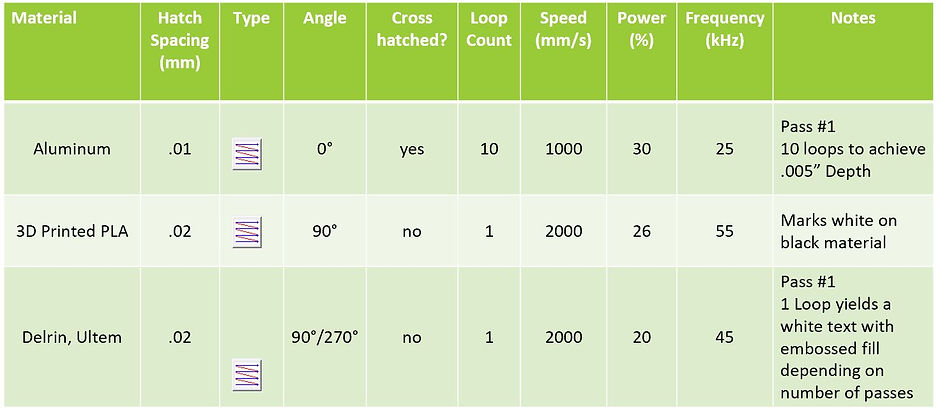
For every material the user can specify laser parameters and hatch settings to get a desired depth of cut or surface finish. Please check the document below to get in-depth details of the material settings when engraving. To summarize, it specifies the hatch pattern used, hatch spacing, angle of hatch, loop count, power, speed and frequency needed for a particular outcome for a specified material.
Flat Surface Engraving
Follow procedure for startup and maintain safety guidelines. PUT Safety Glasses ON! Establish focal point of what is being marked. Place objects in EZCAD to mark. (text/shapes/vector/images)
Use red light to preview and align desired area to mark. Select pens and hatch patterns to match material types. F2/mark/foot pedal when ready to engrave. Every time program is launched a dialogue box will be prompted on the first mark done. The notification can be closed without problem

Flat Surface Capabilities
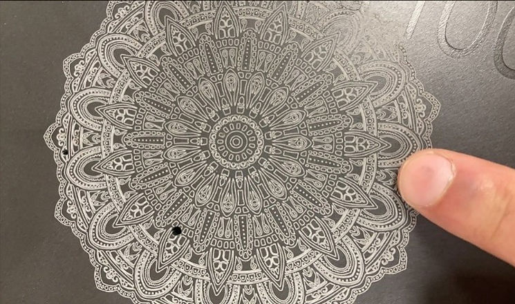
This is just and example of a png image of the Brooklyn bridge that we did to test the capabilities of the laser. The material was anodized aluminum, hence why the picture comes off as white looking, and the cuts of that are relatively weak are black.
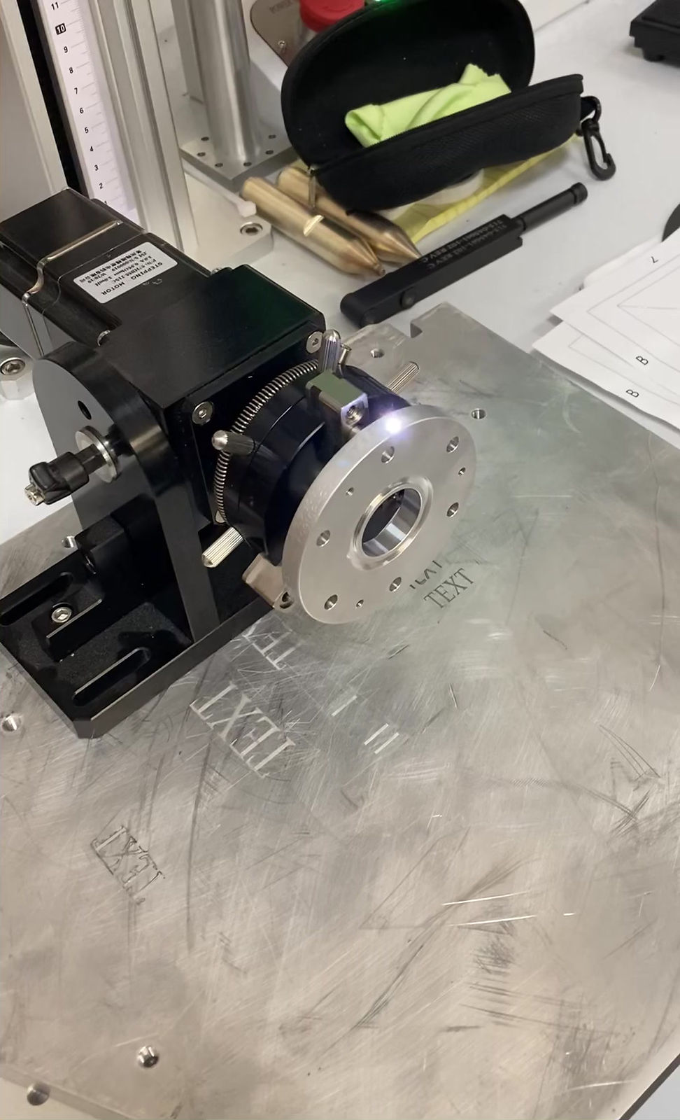
Rotary Attachment
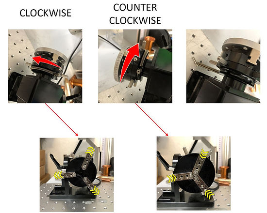
When engraving on cylindrical parts, it may be necessary to mount the part to the rotary tool. The rotary tool can be fixed to the workspace. Adjusting the spring pin tension clockwise/counterclockwise will determine if the clamping force is downward or outward. Button off for rotary tool, locks the gears from spinning when adjusting.

Rotary Engraving Example
Access the RingTextMark tool when marking only text along a cylindrical surface
Step 1. Fill out ring diameter and set correct axis to spin along
Step 2. Recommended to use scrap material and Red button to preview mark letter by letter.
Step 3. Position of part can be manipulated using arrows and distance per step if fine adjustment needed.
Step 4. Mark the part.